Product Overview
How the PKY-60W irrigation controller is used as the core of a standard farm irrigation automation system: pump and valve control, multi-zone scheduling, optional sensors, and irrigation retrofit paths—plus what project inputs we need to recommend a configuration.
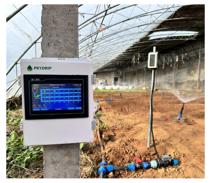
In farm and commercial irrigation, PKY-60W is often deployed not as a standalone device, but as the control core of a complete irrigation control system: coordinating pump and valve control, managing multi-zone operation, and interfacing with optional sensors and expansion modules.
- Pump and multi-zone control in one coordinated system
- Suitable for new irrigation projects and irrigation retrofit work
- Supports pressure and flow monitoring where the project requires feedback
- Expandable for sensor integration and fertigation when needed
- Works with local operation at the cabinet and optional remote communication
System diagram (optional)
When the architecture drawing is ready, add a normal markdown image in this section (for example an SVG under your site’s static images folder) so the page shows one clear figure: PKY-60W, pump control, zone valves, sensors, and field wiring. Until then, this subsection can stay as a short placeholder.
What this standard irrigation control system typically includes
A typical PKY-60W-based setup is built from a small set of standard roles. The exact bill of materials depends on farm size, hydraulics, and pump type—this list describes the usual building blocks, not a fixed kit.
- Main controller: PKY-60W (irrigation controller and system logic)
- Pump control unit (starter / contactor / VFD interface as required by the motor)
- Multi-zone solenoid valves (or valve groups) for distribution
- Main pipeline and control cabinet interface (field wiring, terminals, protection)
- Flow sensor (where flow feedback or totalizing is required)
- Pressure sensor (for pump protection, line pressure checks, or alarm logic)
- Optional touchscreen (local HMI where operators need on-site access)
- Optional remote communication module (e.g. cellular or other link—project-dependent)
Actual configuration always depends on project size, number of zones, and pump and electrical constraints.
What problems this system solves
This page is about outcomes for operators and project teams—not a feature list.
- Automates pump and valve sequencing so irrigation runs follow a defined order
- Reduces repeated manual valve switching and ad-hoc timing
- Improves irrigation scheduling consistency across days and seasons
- Makes zone-based irrigation easier to operate and explain on-site
- Supports irrigation upgrade paths that reuse much of the existing pipeline
- Gives contractors and owners a clear control architecture: one logic core, defined I/O, room to expand
Typical application scenarios
- Open field irrigation — large zones, seasonal schedules, straightforward valve groups
- Orchard irrigation — multiple blocks, staggered runtimes, pressure/flow checks where lines are long
- Greenhouse irrigation — tighter schedules, more frequent cycles, sensor-friendly I/O
- Landscape / municipal green area irrigation — timed programs, limited staffing, reliable unattended runs
- Retrofit of existing manual irrigation systems — replace manual switching with automated sequencing without redesigning the entire field layout
Standard control logic
In plain engineering terms, a typical cycle looks like this (exact parameters are project-specific):
- The irrigation controller enables the pump (or signals the pump controller / VFD) when a scheduled irrigation window starts.
- It opens one zone valve (or a defined valve group) for the active step.
- It uses flow and/or pressure signals when installed—to confirm run conditions, detect faults, or support interlocks.
- Irrigation runs for the scheduled duration or until stop conditions are met.
- The controller closes the zone valve, then advances to the next zone in the program.
- After the last zone in the cycle, it stops the pump and returns to idle or the next schedule.
Sequences, interlocks, and alarm handling can be adjusted to match hydraulic design, electrical limits, and local regulations—the logic above is a baseline pattern, not a fixed firmware script.
Typical system configuration ranges
Small project
- One pump
- Roughly 4–8 zones
- Basic timing control
- Optional pressure sensor for simple line or pump awareness
Standard farm project
- One pump
- Roughly 8–20 zones
- Flow and pressure monitoring where operators need visibility or protection
- More scheduling flexibility (multiple programs, seasonal adjustments)
Expanded project
- Multiple pumps or a higher-power pump train with coordinated pump control
- 20+ zones, sometimes split across valve manifolds or remote valve locations
- Additional sensors (soil, weather, tank level—project-specific)
- Possible fertigation integration via dedicated dosing hardware
- Possible remote communication for alarms, status, or centralized monitoring
Figures are indicative ranges for planning conversations—not guaranteed limits for every site.
What inputs we need to recommend a configuration
Use this checklist when you contact us (copy/paste friendly):
- Farm size (area, rough layout, or map reference)
- Irrigation method (drip, sprinkler, pivot interface, mixed)
- Number of zones (or valve count you need to automate)
- Pump power / voltage (and whether a VFD or soft starter is involved)
- Water source (bore, surface, tank, municipal tie-in)
- New project or retrofit (what exists today: manual valves, old timer, partial automation)
- Whether flow and/or pressure feedback is required (monitoring, protection, billing)
- Whether fertigation is in scope now or later
With this, we can propose a standard irrigation control system layout around PKY-60W instead of quoting a controller alone.
Optional extensions
These items are common upgrades; none are mandatory for every project.
- RS485 sensors (Modbus-class devices on the controller’s field bus)
- Soil moisture probes or soil environment sensors
- Flow meter (dedicated metering where accuracy or reporting matters)
- Pressure sensor (transient protection, dry-run awareness, filter monitoring)
- EC / pH monitoring (quality of irrigation water or nutrient solution)
- Fertigation control (dosing pumps, injectors, tank-linked logic—via compatible hardware)
- LoRa wireless valve control (distributed valves where cabling is costly)
- 4G / cloud communication (remote visibility—subject to network and policy)
Treat these as optional expansions layered onto the same irrigation control system core—not prerequisites.
Who this page is for
This system overview helps:
- Customers starting a new irrigation project who need a realistic control scope
- Customers upgrading manual or semi-automatic systems who want a structured path
- Contractors and integrators comparing a standard control architecture for quoting and installation
- Technical buyers who want a full system recommendation aligned to hydraulics and electricals—not only an irrigation controller SKU
Send your project information for a quick system recommendation
Share zone quantity, pump information (power, voltage, starter or VFD context), water source, and project type (new build vs. irrigation retrofit). Short notes on layout and whether you need flow/pressure feedback are enough for a first-pass irrigation automation layout.
We reply with a practical pump and valve control outline: what typically sits at the cabinet, what stays in the field, and what to phase in later—without turning the exchange into a brochure exercise.
Send zone count, pump details, water source, and project type—we respond with a concise system-level recommendation.
Chat on WhatsApp